The Mystery of the Wandering Drip Edge
Words: Bronzella Cleveland
Robert C. Haukohl, David C. Fortino
Photos courtesy of RRJ and Brick Industry Association
Our first reaction on seeing the photographs was disbelief. A seemingly ordinary five-story, recently-constructed office building, brick masonry veneer supported on shelf angles at each floor, and stainless-steel drip edge pieces sticking out of the building at odd angles looking like they were ready to fall off (Photograph 1). Had there been a wind event? Birds or flying monkeys perhaps?
They couldn't have possibly been installed that way and passed inspection. Did they just sort of wander out on their own? How? None of the options seemed to make sense, but we had to solve this masonry mystery and prevent it from happening in the future.
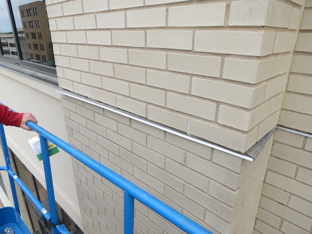 "Wandering" drip edge
Fairly common exterior wall construction: light-gauge steel framing, exterior grade gypsum sheathing, a liquid-applied air barrier/water-resistive barrier, clad with conventional anchored brick veneer. The brick veneer was supported at each floor line by steel shelf angles, with the toes of the shelf angles concealed by either a course of lipped brick below (Photograph 2) or a brick soldier course below cut to fit under the angle (Photograph 3). Flexible, self-adhering membrane flashing and stainless-steel drip edges were present above the shelf angles (Photograph 5).
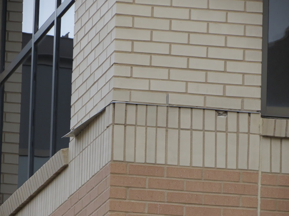 "Wandering" drip edge with lipped brick course below
After an investigation that included destructive testing, a review of the original architectural drawings, and a few mouse clicks on masonry web resources like the Brick Industry Association (BIA) and the International Masonry Institute (IMI), the explanation became clearer. A combination of installation and design decisions with the original lipped brick shelf angle details led to what appeared to be some type of paranormal activity.
 "Wandering" drip edge with linear markings and residue from the self-adhering membrane
INDUSTRY STANDARD DETAILING
Lipped brick is typically used to create horizontal movement joints that aesthetically match the horizontal joint width of other bed joints on the wall, all while concealing shelf angles and steel lintels. Lipped brick design details provided by BIA (Figure 1) and IMI provide a compressible material (inboard) and a sealant joint with backer rod (outboard) between the shelf angle and the brick course below. The compressible material and the sealant are "soft" materials that allow for movement of the brick below relative to the shelf angle and brick above.
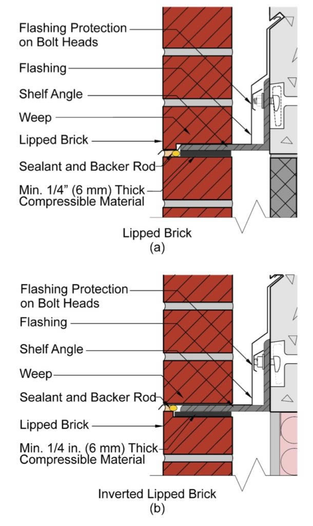 BIA Lipped Brick Details (Courtesy of BIA)
A key consideration when constructing the detail is allowing movement of the brick installed below the shelf angle. To achieve this, no rigid contact should occur between the bricks above and below the shelf angle, or between the brick below and the shelf angle itself. One of the theoretical advantages of the lipped brick detail is that the lip does not have to be field cut, thus reducing the labor involved in constructing the detail.
However, this is only achievable if the shelf angle aligns perfectly with the horizontal joint in the brick. Unfortunately, these conditions rarely happen in the field due to construction tolerances, or due to lack of coordination between the ironworker and mason. To accommodate a shelf angle that does not align with brick veneer coursing, the course below the shelf angle is often field cut to align with the shelf angle.
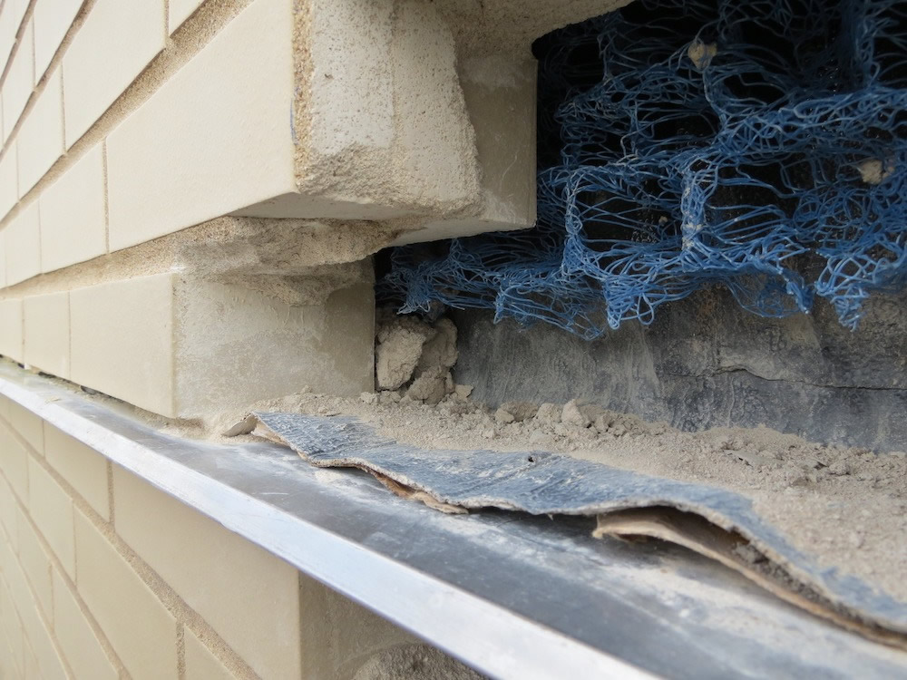 Self-adhering membrane flashing without backing paper removed
OBSERVATIONS
The investigation started with a visual and telescopic examination of the brick veneer on the building exterior. A close-up hands-on examination of the veneer was performed and with destructive test cuts made at several representative locations. At approximately 20 brick support locations around the building, the stainless steel drip edge had displaced laterally parallel to and/or out from the wall (Photographs 1 through 3).
In some places, the drip edge had almost completely worked its way out of the wall. When attempts were made to pull the displaced drip edges free by hand, they remained stubbornly stuck in the wall. Linear markings were present on the top surfaces of the displaced drip edges (Photograph 4) and cracked and displaced brick was often observed in the course below the displaced drip edges (Photograph 3).
Oddly, at most of the investigative openings, the shelf-adhering membrane was not adheredto the shelf angle or drip edge because the backing paper had not been removed from the adhesive side of the membrane (Photograph 5). At no investigative opening did the shelf angle align with the horizontal joint in the veneer.

The brick course below the shelf angles had been field cut to accommodate the shelf angle, and had been placed such that the lip of the brick was tight to the underside of the drip edge without a sealant joint to separate the two materials (Photograph 6) and/or tight to the underside of the shelf angle without a compressible filler to separate the two materials (Photograph 7).
DRAWING REVIEW
The shelf angle brick support cross-section details in the architectural drawings did not help much in providing a clear intent for a horizontal movement joint between materials at these locations. One detail showed the lip of the brick tight to the underside of the drip edge with a mortar bed joint above the drip edge (Figure 2).
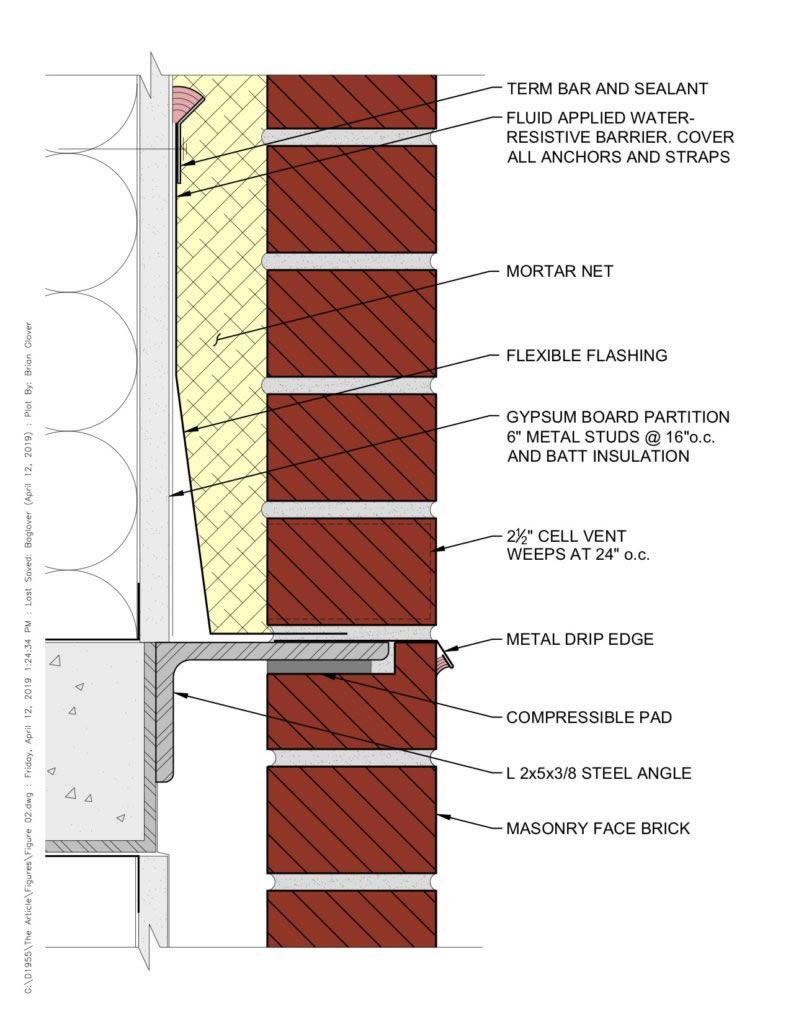 Lipped brick detail configuration as depicted in architectural drawings (Redrawn by RRJ)
Another detail showed mortar between the lip of the brick and the underside of a "prefinished brake metal flashing" with the flashing tight to the underside of the brick course above. Neither detail depicted the proper integration of "soft" materials to allow for horizontal movement along the joint, and no indications of a "prefinished brake metal flashing" were observed on the building as shown in the second detail.
MYSTERY SOLVED
The design for the shelf angle brick support locations, as depicted in the architectural drawings, was not consistent with industry standard details, and did not provide a soft joint between the lip of the brick and the underside of the drip edge to accommodate differential movement between the brick above and below the shelf angle.
An attempt was made by the mason to construct the detail similar to how it was shown in the drawings, although at each investigative opening, the shelf angle did not perfectly align with the horizontal joint in the brick, necessitating field cutting of the brick course below to accommodate the shelf angle. The resulting as-constructed detail still did not allow horizontal movement of the brick veneer at lipped brick locations.
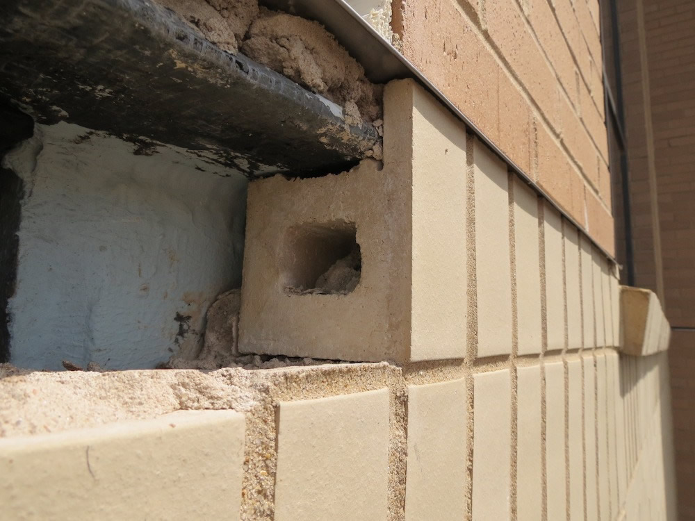 Field-cut running bond course of brick with lip tight to the underside of the drip edge
The metal drip edge became pinched and, lacking restraint, gradually "wandered" laterally parallel to and/or out from the wall due to differential movement between the brick above and below the drip edge. Was the presence of the flashing backing paper a major factor?
The authors believe it unlikely, as some of the linear markings on the displaced drip edges contained black residue from the flashing adhesive, so in places where the flashing adhered, the adhesive still wasn't strong enough to keep the drip edges from "wandering" away from their original locations. Lack of backing paper does lead to another problem though—lack of a watertight seal between the flashing and the drip edge, creating the potential for water infiltration issues.
REPAIR
Restoration of the shelf angle detail required (1) modification of the detail in order to create a horizontal movement joint to accommodate moisture and thermal movement of the brick veneer using a "soft" compressible material, (2) resetting the displaced drip edges and properly integrating them with the self-adhering flashing, (3) replacement of cracked and spalled bricks, and (4) sealing the underside of the drip edge to the masonry below to create a watertight joint using a "soft" material. It was an expensive repair approach requiring removal and replacement of brick above and below the shelf angle to gain access and perform the repairs.
Although the flying monkey theory was the initial favorite, the answers to the mystery were a bit more straightforward. With the availability of industry standard detailing, and with attention to detailing and coordination among trades, the shelf angle flashing detail shouldn't have to be a mystery.