 Figure 1a – Masonry pilaster Figure 1b - Steel column
Experience has shown that 4-foot-wide piers without added lateral support will satisfy many pier conditions. However, every design must be analyzed for the project-specific conditions.
Let us discuss some things that can be done to create a narrow pier.
- The type of headers selected can have a significant effect on the structural performance of the piers.
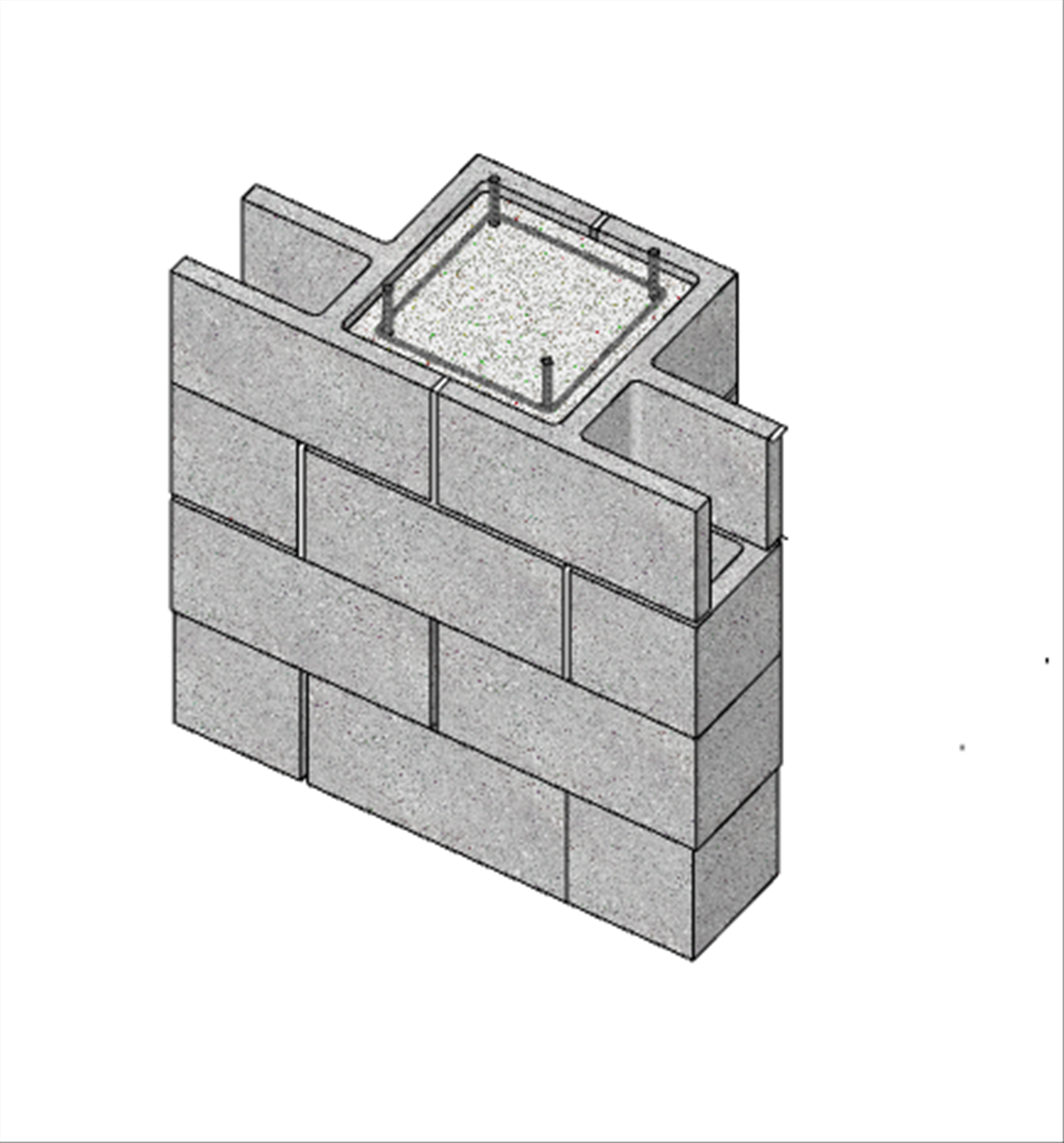
- Reinforced masonry headers (beams) are ideal for masonry walls. The masonry construction integrates seamlessly from the piers to the headers and the wall area above (Figure 2). The masonry headers can bear on or continue through the piers. This all-masonry construction means the vertical reinforcement of the jambs which can pass through the header so that the full pier width is effective in both compression and tension.
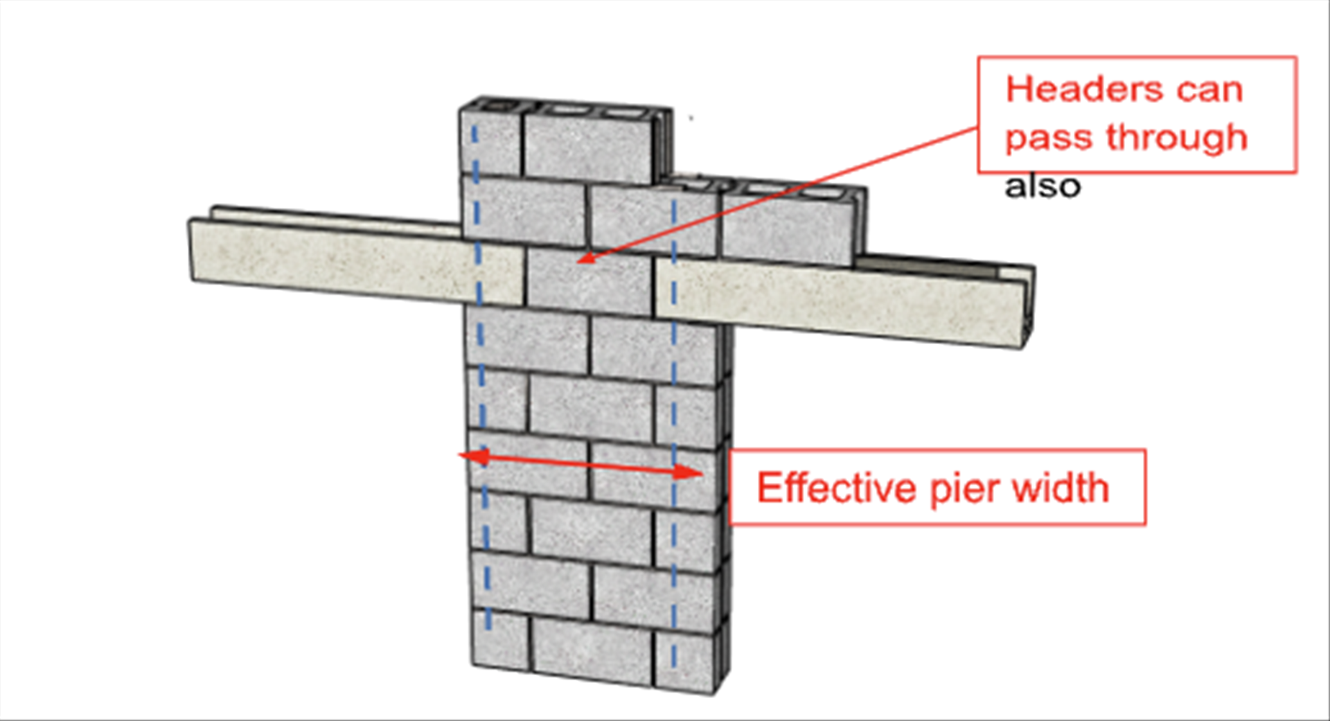
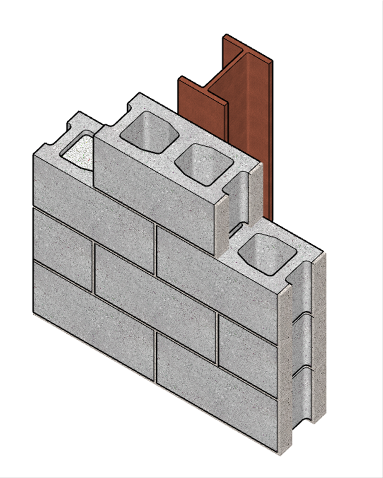
Figure 2 – Masonry headers at a pierSteel headers are sometimes used, but they create detailing and design issues. The steel headers bearing on a pier interfere with the vertical reinforcement and effectively reduce the net masonry section available to resist lateral loads (both out-of-plane and in-plane) (Figure 3). The result is that the use of steel headers will likely require wider piers to compensate for the steel bearing area.
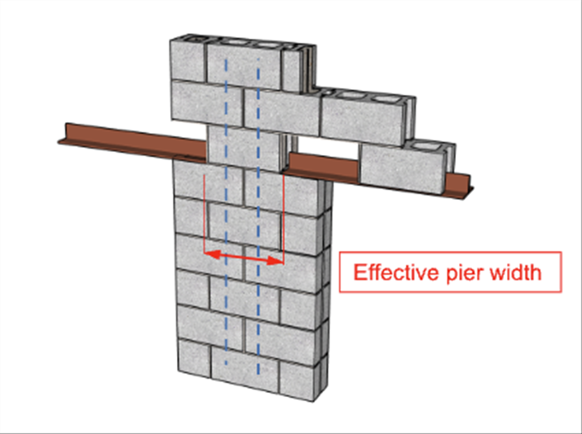 Figure 3 – Steel headers at a pie
r
The magnitude and load path through the piers always affect the required pier size. In all cases, the masonry pier (single wythe or the backup wall for a cavity wall) must be able to support the vertical loads. This includes bearing stress on the pier from the headers and the compression from the wall above.
The pier size is also affected by the lateral loads, out-of-plane and in-plane. If the pier cannot support the vertical and lateral loads simultaneously, the pier can be reinforced by a masonry pilaster or a column (steel or concrete) to provide lateral support (Figure 1).
- Using a pilaster, the composite section of the masonry wall and pilaster can be designed for the full loads (vertical and lateral loads).
- Using a column, the masonry supports the wall vertical loads; the column supports the out-of-plane lateral loads; and a rigid frame might be needed with the column. Each project needs to be evaluated independently.
Summary:
- Use masonry headers whenever possible.
- To minimize masonry pier widths without adding pilasters or columns, check four-foot-wide piers first. If that works, the structural analysis will inform you as to whether the pier could be designed narrower.
- If four-foot piers are not narrow enough, you may have to resort to using a pilaster or column, and even a frame.
Q. A Mason Contractor asks about horizontal soft joints in a brick veneer with lipped brick under shelf angles. They constructed a building approximately 10 years ago, and just recently, the building Owner hired a firm to inspect for deteriorated or damaged sealants. Comments the Owner received from the inspector were that there was a minimal gap below the shelf angles, the sealants had been over-compressed, and the brick should have been installed with a larger gap. How should we respond to the Owner?
A. This is an interesting question. We will address the technical issues, not the legal ones.You also stated that the shelf angles are spaced approximately 17 feet vertically, there was no cracking in the lipped bricks above or the stretcher bricks under the shelf angle (5/16 inches thick), there was no compressible filler under the angle, the soft joint size below the angle is now approximately 1/8 inch and the original joints are 3/8 inches, and that the building had a concrete frame. That is important information. Some comments are:
a. Assuming the sealant joints under the lipped edge and the shelf angles were 3/8 inches originally, the change in joint size has been approximately 1/4 inch.
b. The brick veneer has undergone expansion, both irreversible moisture growth and seasonal thermal expansion, without causing masonry distress, but most of the sealants have failed. The Brick Industry Association (BIA), Tech Note 18, charts the likely moisture expansion over 4.5 years (Figure 4). Extending that graph to ten years, it is likely the moisture expansion is about 80% of its expected growth.
TMS 402 gives a coefficient of moisture expansion for clay masonry as 3 x 10⁻⁴ in./in. For the 17-foot veneer height, which translates to 0.06 inches. If the veneer has experienced 80% of its moisture growth, that would account for 0.05 inches. The remaining growth would be approximately 0.01 inches.
From TMS 402, thermal expansion could account for 4 x 10⁻⁶ in./in./°F (coefficient of thermal expansion) x 60° (assumed temperature change for the site) = 0.05 inches.
Combined, the calculated expansion amounts to 0.10 inches, less than 1/8 inch.
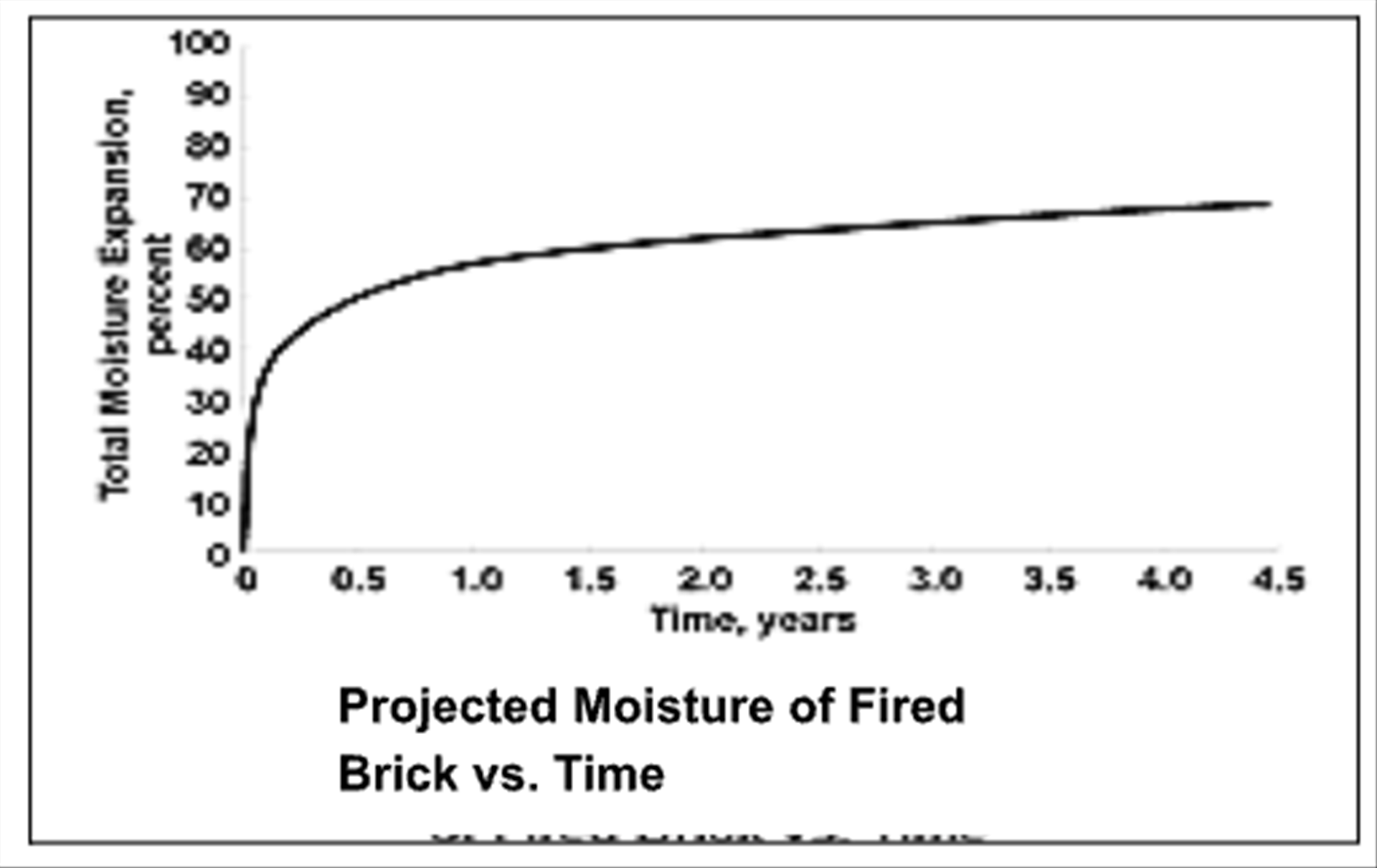 Figure 4 – BIA Figure 2 from Tech Note 18 (courtesy of BIA)c.
 An added factor for consideration is the building’s concrete frame. Over time, the concrete frame shrinks, and that movement is also reflected in the sealant joint compression. Much more information is required to estimate the shrinkage, but it could be significant.
d. The Brick Industry Association (BIA) recommended detail for shelf angles with lipped bricks is shown in Figure 5. They recommend the compressible material below the angle, and the sealants be chosen to accommodate the anticipated movement. BIA also notes that the anticipated joint movement should not exceed the compression capacity of these materials; most have a minimum capacity of 50% in tension and compression. Since your project had no compression material below the angle, the controlling compression is due to the sealant. If the sealant joints were initially installed 3/8 inches thick, they would likely have had a movement capacity of 3/16 inches.
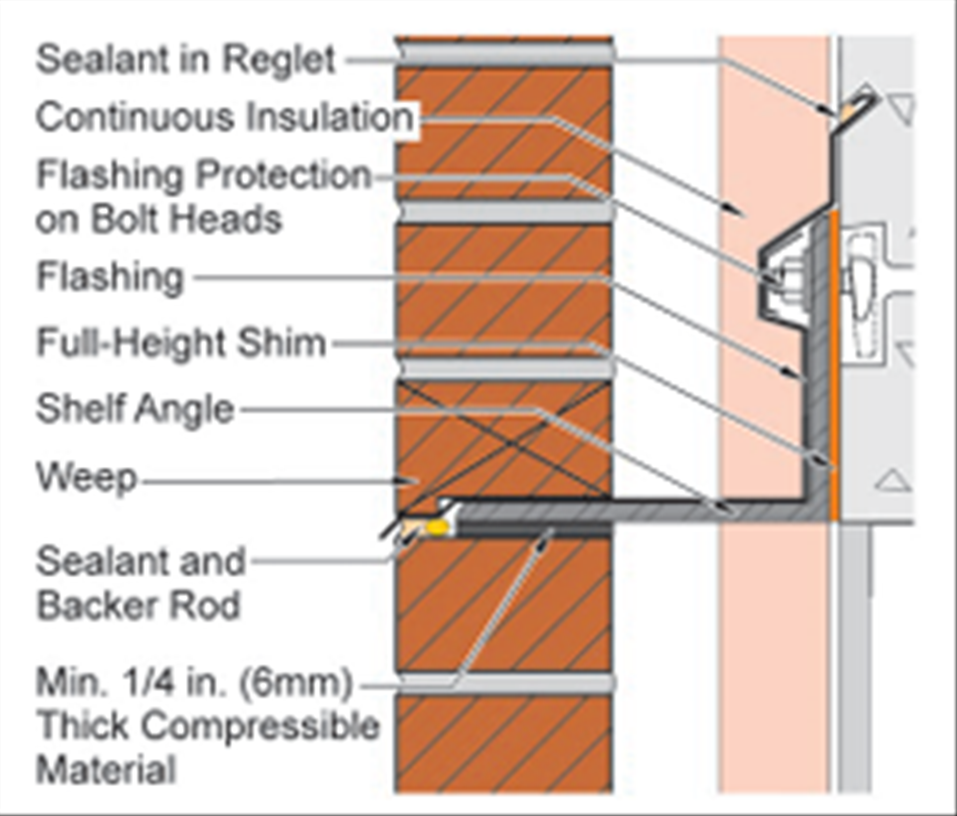 Figure 5 – BIA Figure 8 from Tech Note 18A (courtesy of BIA)
To recap:
a. the soft joint for the sealant and the gap under the shelf angles was 3/8 inches, and it has closed 1/4 inch, still leaving a 1/8 inch gap.
b. the calculated expansion to date is 0.10 inches, with 0.01 inches still expected.
c. the shrinkage of the concrete frame is unknown
Therefore, there is still a sufficient gap beneath the angle to accommodate the remaining expected expansion of the veneer. If the remaining expansion of the veneer does occur, the total will be 1/8 inch. Yet the movement has already been 1/4 inch.
So, what is the problem? The veneer seems to be performing as expected, but the sealants have failed. The initial 3/8 inch gap has been adequate to accommodate the veneer expansion. However, concrete frame shrinkage should be evaluated for its contribution to the movement.
Several assumptions were made to answer your question, which should be confirmed. And, the sealant should be scrutinized. Did it not have sufficient compression capacity to accommodate the anticipated brick expansion and the anticipated shrinkage of the concrete frame? Should the soft joint have been larger to accommodate the concrete shrinkage and brick expansion without overcompressing the sealant?
Summary:
- Soft joints need to be sized for the anticipated movement of both the veneer and the building frame.
- A concrete frame will shrink, and that movement must be considered in sizing the soft joints.
- Brick moisture growth can occur over many years.
- Sealants are a key component in joint design. The % compression capacity must be considered to prevent over-compression.
___Thank you again for following this column. Remember, by bonding, we get stronger! Keep the questions coming. Send them and your comments to info@masonrymagazine.com, with attention to Technical Talk. If you have missed any of the previous articles, you can find them online for Technical Talk, Bonding with Masonry at Masonry Design magazine
(https://www.masonrydesignmagazine.com/?s=biggs).
David is a PE, SE with Biggs Consulting Engineering, Saratoga Springs, NY, USA (www.biggsconsulting.net), and an Honorary Associate Professor with the University of Auckland, NZ. He specializes in masonry design, historic preservation, forensic evaluations, and masonry product development.
Keywords for this issue: piers, lintels, pilasters, shelf angles, soft joints, sealants, concrete shrinkage